
A solar array does not produce exactly the same amount of power throughout the day. Output rises as sunlight increases, typically peaks around the strongest solar conditions, and falls again later in the day. The inverter must continuously convert that variable DC electricity from the solar panels into usable AC electricity.
But what happens when the panels are capable of producing more power than the inverter can convert? The result is solar inverter clipping.
Clipping is sometimes interpreted as evidence that an inverter is too small or that energy is being unnecessarily wasted. In reality, a certain amount of clipping can be an intentional consequence of system design. Solar arrays are frequently designed with more DC module capacity than AC inverter capacity because modules rarely operate at their nameplate rating for extended periods under real-world conditions.
The key is understanding the balance. Too little DC capacity can leave an inverter underutilized, while excessive oversizing can increase clipping and potentially reduce the economic value of additional modules.
What Is Solar Inverter Clipping?
Solar inverter clipping occurs when the DC power available from a PV array exceeds the amount of power the inverter can convert to AC at that moment.
Imagine a PV array capable of supplying 120 kW DC connected to an inverter with a maximum AC output of 100 kW. Under conditions where the array could deliver enough DC power for more than 100 kW of AC output, the inverter remains limited by its rated AC capacity. The portion above that limit is effectively clipped.
On a system’s production graph, this can create a flattened section at the top of what might otherwise resemble a smooth bell-shaped production curve. Clipping should not automatically be confused with an inverter malfunction. It can occur during normal operation in a deliberately oversized PV system.
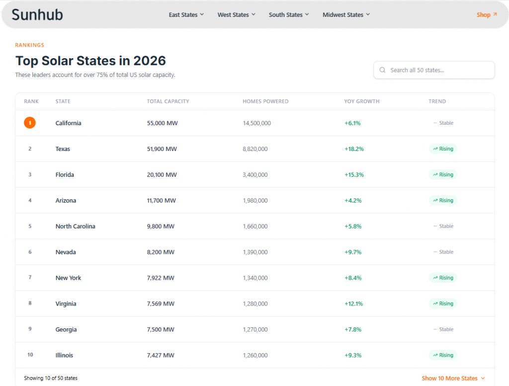
Explore U.S. Solar State Rankings
Compare solar rankings, installed capacity, growth trends, and market performance across all 50 states. Discover regional insights to support smarter procurement and expansion decisions.
Understanding the DC-to-AC Ratio
To understand clipping, it helps to understand the DC-to-AC ratio, also known as the inverter loading ratio (ILR).
DC-to-AC ratio = PV array DC nameplate capacity ÷ inverter AC nameplate capacity
For example, a 120 kW DC solar array paired with a 100 kW AC inverter has a DC-to-AC ratio of 1.20. NREL research evaluating inverter clipping has examined ILRs of 1.2, 1.3, 1.4, and 1.5 as representative of the range commonly found in newer PV systems.
The appropriate ratio, however, is project-specific. Climate, module orientation, temperature, inverter characteristics, utility requirements, system losses, and project economics all matter.
Solar Inverter Clipping at Different DC-to-AC Ratios
The following simplified table illustrates how changing the DC array size affects the potential for clipping when the inverter remains at 100 kW AC.
| DC array size | Inverter AC rating | DC-to-AC ratio | General clipping potential |
|---|---|---|---|
| 100 kW | 100 kW | 1.00 | Lower |
| 110 kW | 100 kW | 1.10 | Relatively low |
| 120 kW | 100 kW | 1.20 | Moderate under strong production conditions |
| 130 kW | 100 kW | 1.30 | More frequent clipping may occur |
| 150 kW | 100 kW | 1.50 | Greater clipping potential |
| 200 kW | 100 kW | 2.00 | Significant modeling and economic evaluation required |
These descriptions are illustrative rather than universal design recommendations. Two systems with identical ratios can experience different clipping losses because of location, weather, array orientation, module temperature, equipment characteristics, and other factors. NREL research has demonstrated that accurate clipping analysis becomes increasingly important at higher ILRs.

Why Would Designers Intentionally Oversize the Solar Array?
At first glance, matching 100 kW of solar modules with exactly 100 kW of inverter capacity may seem like the obvious solution. Real solar systems are more complicated. A module’s nameplate power is established under standardized test conditions. Those conditions do not represent every hour of real-world operation.
Actual module output changes with factors including solar irradiance, cell temperature, cloud cover, module orientation, shading, soiling, system losses, and module degradation.
As a result, a 100 kW DC array does not continuously send 100 kW to its inverter. Adding more DC module capacity can allow an inverter to operate at higher output for longer portions of the day, particularly during periods when the array is producing below its theoretical maximum. The tradeoff is that when production becomes particularly strong, the inverter may reach its maximum output and clipping occurs.
Why Some Clipping Can Be Acceptable
The existence of clipping does not by itself mean a PV system has been designed poorly. Suppose increasing an array from 100 kW DC to 120 kW DC produces considerably more electricity during mornings, afternoons, winter months, cloudy conditions, and other lower-production periods. During a limited number of high-production periods, the inverter might clip some output.
The additional annual energy generated by the extra 20 kW of modules may still outweigh the electricity lost through clipping. This is ultimately an optimization problem. The objective is not necessarily to achieve zero clipping. Instead, designers can seek the combination of modules and inverter capacity that delivers appropriate lifetime energy production and project economics.
What Does Solar Inverter Clipping Look Like?
Under idealized conditions, solar production often follows a curve: low production in the morning, increasing production toward midday, followed by declining production in the afternoon. When clipping occurs, the top of that curve may flatten.
For example, an inverter rated for 10 kW AC might show output rising normally throughout the morning until reaching approximately its operating limit. Rather than continuing upward with available DC power, AC output remains around that limit until solar production falls sufficiently.
Monitoring data can therefore provide an early indication of clipping. However, a flat production curve does not automatically prove that clipping is occurring. Export limits, plant controls, grid curtailment, thermal derating, or other operating conditions can potentially create similar patterns.
What Factors Increase Solar Inverter Clipping?
High DC-to-AC ratios
Increasing module capacity while maintaining the same inverter AC rating increases the possibility that available DC power will exceed the inverter’s conversion capability.
Strong solar irradiance
High irradiance can increase module production and push inverter output toward its limit.
Cooler module temperatures
Solar module power generally decreases as cell temperature rises. Bright conditions combined with relatively cool module temperatures can therefore produce particularly strong DC output.
Array orientation
Orientation affects when different portions of an array reach peak production. A system with modules facing primarily in one direction can have a different production curve from a system divided across multiple orientations.
Low system losses
A high-performing system with relatively low losses may deliver more DC power to the inverter than initially expected under favorable conditions.
How Much Solar Inverter Clipping Is Too Much?
There is no universal percentage that defines acceptable clipping for every project. Designers need to evaluate the value of additional DC capacity against the energy that will be clipped.
If increasing a system’s DC-to-AC ratio produces significantly more annual electricity while causing relatively little additional clipping, oversizing may make economic sense. At some point, however, each additional module can produce diminishing returns because an increasing portion of its possible output occurs when the inverter is already operating at maximum capacity.
NREL research shows why clipping should be incorporated carefully into energy-yield modeling. Studies comparing subhourly clipping models found that improved modeling methods could estimate annual clipping losses more accurately than simple hourly power-limit approaches, particularly as ILRs increase.
Clipping vs. Curtailment vs. Inverter Derating
Clipping occurs because available DC power exceeds the inverter’s maximum conversion or output capability.
Curtailment occurs when the system is intentionally instructed to reduce output, potentially because of grid requirements, export restrictions, plant controls, or market conditions.
Derating occurs when an inverter’s available output is reduced because of operating conditions, such as excessive temperature or another equipment limitation.
Does Inverter Clipping Damage the Inverter?
Normal clipping within the inverter manufacturer’s permitted design and operating limits is not inherently evidence that the inverter is being damaged. PV inverters are designed to regulate power conversion within defined electrical limits.
However, system designers must follow manufacturer requirements for maximum DC voltage, current, power, string configuration, temperature, and other electrical parameters. A project’s acceptable DC-to-AC ratio should never be determined solely by how much clipping the owner is willing to accept.
How to Reduce Excessive Solar Inverter Clipping
Increase inverter capacity
Using an inverter with a larger AC rating can provide more conversion capacity during periods of high production. The tradeoff is higher equipment cost and potentially lower inverter utilization during periods of weaker production.
Reduce DC oversizing
Reducing the number or capacity of modules lowers the DC-to-AC ratio and can reduce clipping. However, it can also decrease production during lower-irradiance periods.
Optimize array orientation
Spreading module production across different orientations can potentially create a broader generation profile instead of concentrating production around the same peak period.
Reevaluate the system through energy modeling
Before changing equipment, model the alternatives. Compare annual energy production, clipping losses, equipment costs, utility requirements, and project economics across several inverter and array configurations.
Choosing the Right Solar Inverter
Managing clipping begins with selecting an inverter appropriate for the PV array and project design. Important specifications include rated AC power, maximum DC input voltage, MPPT voltage range, maximum input current, number of MPPT channels, conversion efficiency, manufacturer-approved DC oversizing, environmental ratings, grid requirements, warranty, and monitoring capabilities.
Inverter type also matters. String inverters, central inverters, microinverters, and hybrid inverters serve different system architectures and project requirements. Installers, EPCs, developers, and other solar professionals can explore solar inverter listings on Sunhub when sourcing equipment for upcoming projects.
Solar Inverter Clipping and Long-Term System Performance
Clipping can also change as a PV system ages. Solar modules gradually degrade over time, meaning their maximum output generally decreases. As the available DC power declines, the system may reach the inverter’s AC limit less frequently.
Research from NREL has noted that degradation can make clipping less frequent as systems age. This creates another consideration when optimizing the initial DC-to-AC ratio. A system designed to eliminate virtually all clipping during its first year may have even more unused inverter capacity later in its operating life.
Why Accurate Clipping Modeling Matters
Clipping directly affects predicted energy yield. If a financial model assumes every unit of available DC power can be converted to AC electricity, it may overestimate generation from an oversized system. On the other hand, avoiding DC oversizing simply because some clipping occurs can also result in a system that generates less annual electricity than an optimized design.
Modern PV modeling should account for hourly or subhourly irradiance, module temperature, array orientation, system losses, inverter efficiency, DC-to-AC ratio, clipping, and degradation.
Conclusion
Solar inverter clipping occurs when the power available from a PV array exceeds the inverter’s ability to convert that power into AC electricity. Although clipping represents energy that is not converted, it is not automatically a design problem.
Solar arrays are often intentionally designed with more DC module capacity than AC inverter capacity. Doing so can increase production during mornings, afternoons, weaker irradiance, and other periods when the modules are operating below their rated capacity.
For installers, EPCs, developers, and system designers, the best approach is to evaluate the DC-to-AC ratio alongside local weather, module characteristics, inverter specifications, array orientation, utility requirements, annual energy yield, and project economics. Clipping is not necessarily something to eliminate. It is something to understand, model, and optimize.
Frequently Asked Questions
What is solar inverter clipping?
Solar inverter clipping occurs when the available DC power from a solar array exceeds the inverter’s maximum AC output capability. The inverter limits its output rather than converting all of the available DC power.
Is inverter clipping bad?
Not necessarily. Some clipping can occur in intentionally oversized PV systems and may be economically acceptable if the additional DC capacity produces enough extra energy during other periods to compensate for clipped production.
What is the DC-to-AC ratio?
The DC-to-AC ratio, or inverter loading ratio, compares the solar array’s DC nameplate capacity with the inverter’s AC nameplate capacity. A 120 kW DC array paired with a 100 kW AC inverter has a ratio of 1.2.
What DC-to-AC ratio causes clipping?
There is no single ratio at which every system begins clipping. Clipping depends on irradiance, temperature, orientation, equipment characteristics, system losses, and other factors.
Can a larger inverter eliminate clipping?
Increasing AC inverter capacity can reduce clipping, but it can also increase equipment cost and leave more inverter capacity unused during lower-production periods. The economic effect should be modeled before changing inverter size.
How can I tell if my solar inverter is clipping?
Monitoring data may show a flattened production curve when inverter output reaches its maximum level. Similar patterns can result from curtailment, export controls, or other operating conditions, so system data should be evaluated carefully.
Sources
- National Renewable Energy Laboratory: The Effect of Inverter Loading Ratio on PV Performance
- National Laboratory of the Rockies: Quantifying the Impact of Inverter Clipping on Photovoltaic Performance and Soiling Losses
- National Laboratory of the Rockies: Side-by-Side Comparison of Subhourly Clipping Models